By BD7OTO
M17 与 OpenRTX
1. The basics
In 2010, David Rowe, VK5DGR, released Codec2 as open source, an open-source voice codec running at just 700–3200 bit/s. In 2012 came FreeDV, a digital amateur radio project built on Codec2 for HF, where the low frequencies keep the codec in its low-rate modes. In 2019, Wojciech Kaczmarski, SP5WWP, of Warsaw, Poland, launched M17, a digital radio protocol also built on Codec2 — but for VHF and above, and fully open source, avoiding the proprietary licensing restrictions of the commercial protocols (DMR, P25, C4FM, D-STAR).
Since the 1990s, amateur digital voice had moved slowly, with most operators relying on commercial digital protocols. M17 gives hardware and software developers who love radio a platform to show what they can do. In December 2024, the M17 Foundation was established, giving developers the legal backing they needed.
2. The technical points
As everyone knows, DMR uses TDMA, while M17 uses FDMA — the two are incompatible.
The physical layer uses 4-FSK modulation, achieving a 9600 bps channel rate in a 12.5 kHz channel. For the details, see the English-language M17 Protocol Specification, Part I — Air Interface.
The author would like to say one thing: don’t let anyone tell you English doesn’t matter. For anyone doing serious science and engineering, English is the mother tongue. And don’t let anyone tell you math doesn’t matter either — math is the foundation of science and engineering.
OpenRTX is free, open-source firmware for digital amateur radio, and it now supports M17 as well.
3. How to get on M17
3.1 Radios with native M17 support
The following handhelds support M17 natively:
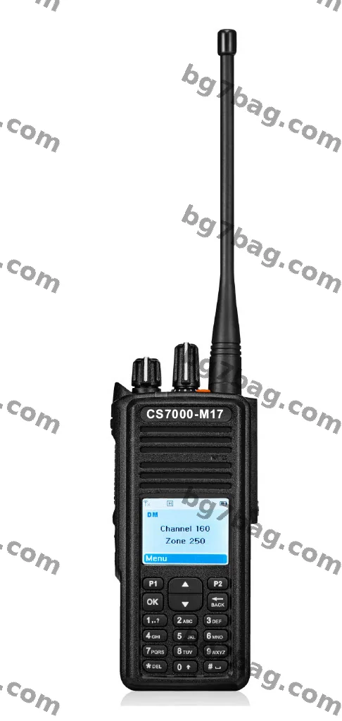
Connect Systems CS7000-M17 手持电台
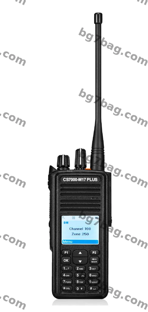
Connect Systems CS7000-M17 Plus 手持电台
- CS7000
- CS7000 Plus
The CS7000 and CS7000 Plus are handhelds from Connect Systems that run OpenRTX firmware and support M17 natively.
3.2 Some DMR radios can gain M17 support
By flashing OpenRTX firmware with a simple hardware modification:
- Baofeng DM-1701 — flash OpenRTX firmware. Mod guide: https://github.com/M17-Project/DM-1701_mod
- TYT MD-380, MD-390 — flash OpenRTX firmware. Mod guide: https://openrtx.org/#/M17/md380_mods
- Retevis RT3 (UHF) — same as the MD-380
- TYT MD-UV380, MD-UV390 — flash OpenRTX firmware. Mod guide: https://openrtx.org/#/M17/mduv380_mods
- Retevis RT3S — flash OpenRTX firmware
3.3 This is the heart of the article
Some ordinary analog FM radios can support M17 with the help of Module17. Module17 is a compact M17 modem that gives a traditional analog FM radio (with a 9600 bps packet interface) the ability to run M17. The photos below show the author’s own Module17 board build.
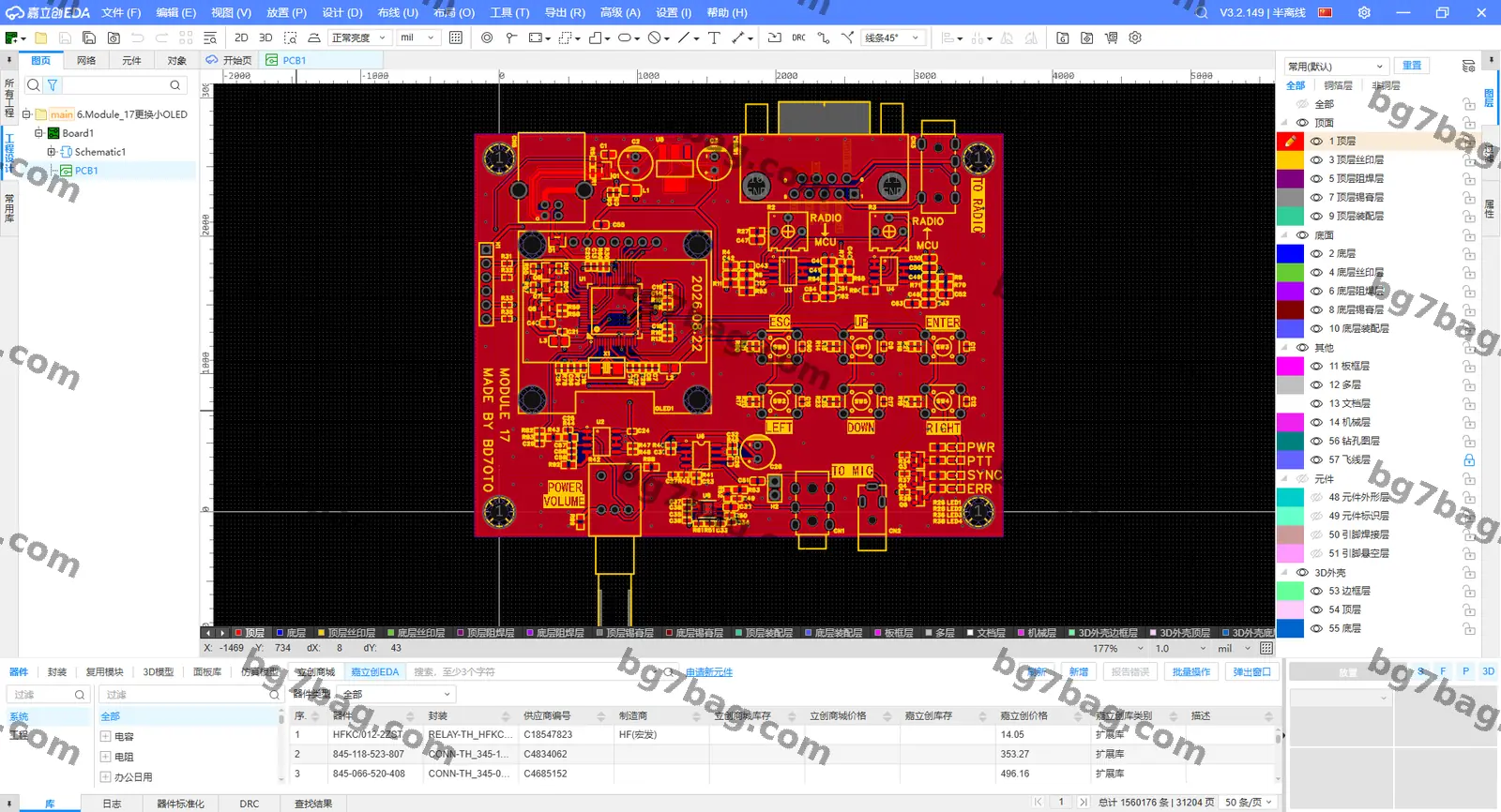
Module17 的 PCB 布线图(立创 EDA)
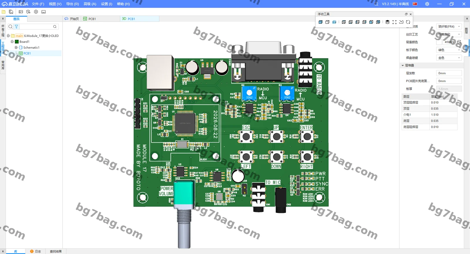
Module17 的 PCB 3D 视图
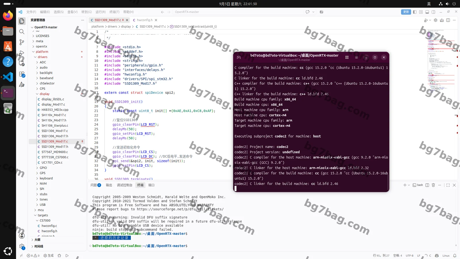
编译 OpenRTX 源程序
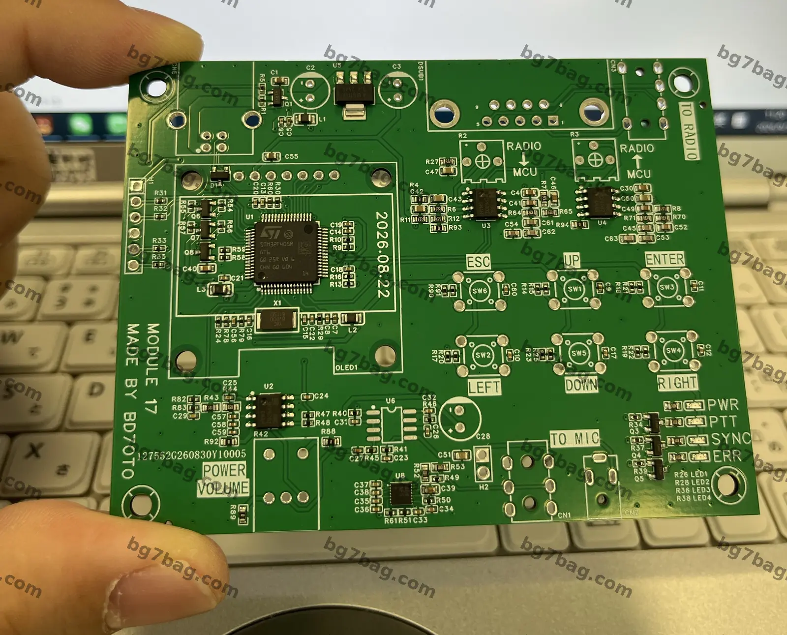
Module17 裸板
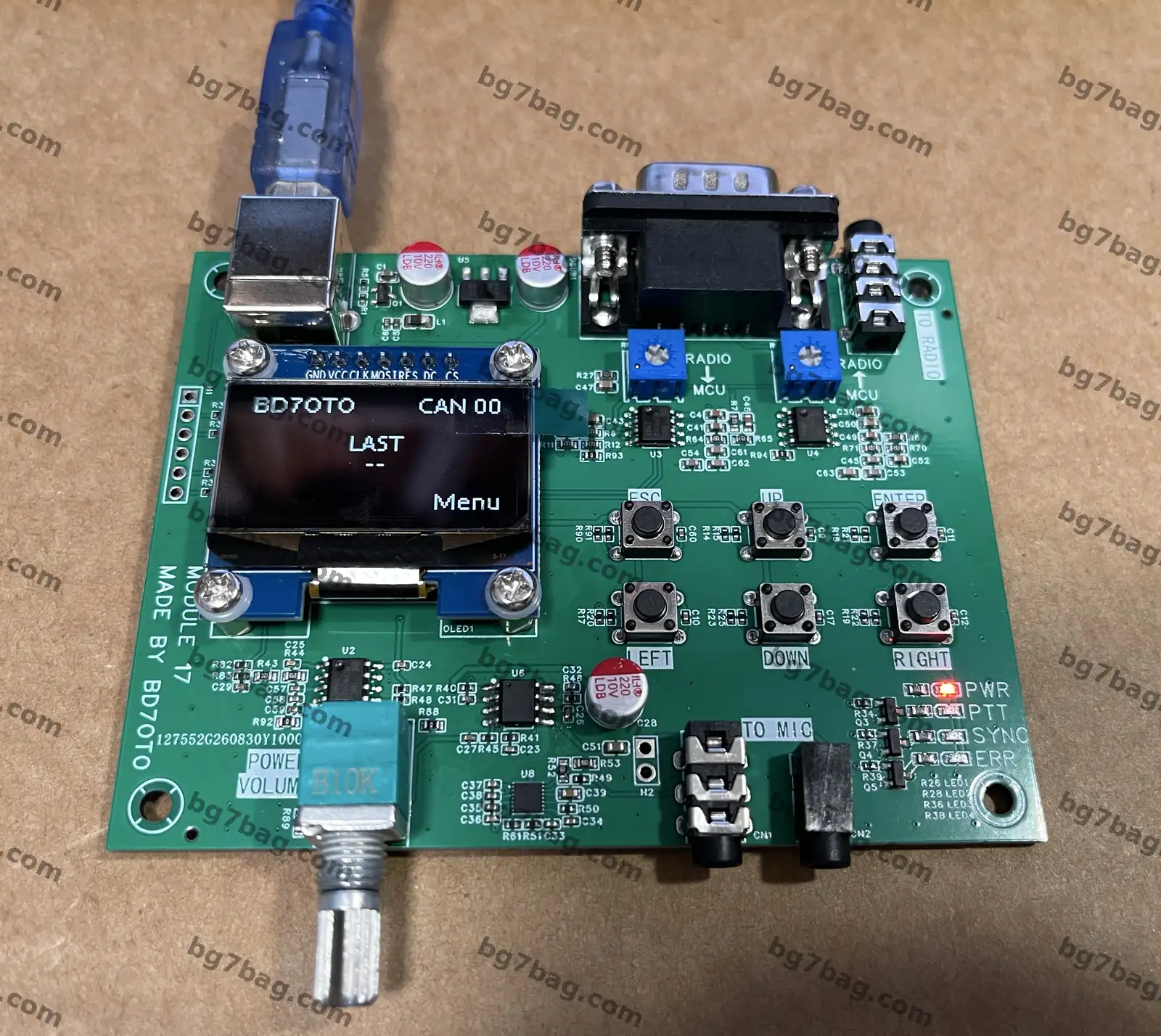
贴片完成后的 Module17 成品板
For analog radios that support Module17, see: https://wiki.m17foundation.org/index.php?title=Radio_compatibility_list
Power: USB Type-B (the printer-style square connector). USB-C power delivery specifications remain inconsistent, so after much thought I decided against it.
DB9 connector: the interface between Module17 and the radio.
Using the Yaesu FTM series as an example, the cable pinout is shown below.
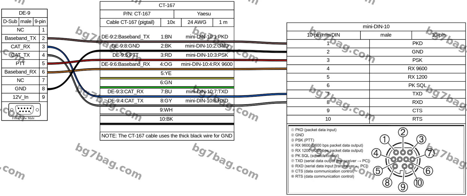
Module17 与八重洲 FTM 的接线图
Microphone jack: for a Baofeng hand microphone (with built-in speaker). Other brands have not been tested yet.
Volume knob: bottom left — power switch and volume control for the mic’s speaker.
Question 1: What’s the difference between Yaesu’s 1200 bps and 9600 bps packet data output?
The 1200 bps output is commonly used for VHF APRS. It sends data as two audio tones, which pass through the audio chain, including pre-emphasis and filtering. The 9600 bps output bypasses the audio processing entirely, so the signal passes through undistorted.
Question 2: What’s the difference between Yaesu’s DIG and PKT modes?
| DIG mode | PKT mode (a subset of DIG) | |
|---|---|---|
| Core use | Digital voice and demodulation of various digital modes | Packet data only, 1200/9600 bps |
| Typical use | C4FM digital voice, FT8 weak-signal | APRS position reports, data messages |
| Hardware | The radio’s built-in DSP handles the basics | Needs an external TNC/data adapter and a computer |
| Rates | No fixed rate — depends on the protocol | Fixed 1200 bps (standard VHF) and 9600 bps (high-speed data) |
3.4 Future radios
The M17 team is currently developing LinHT — an open-source, Linux-based SDR handheld radio. Its mainboard resembles the Retevis C62’s.
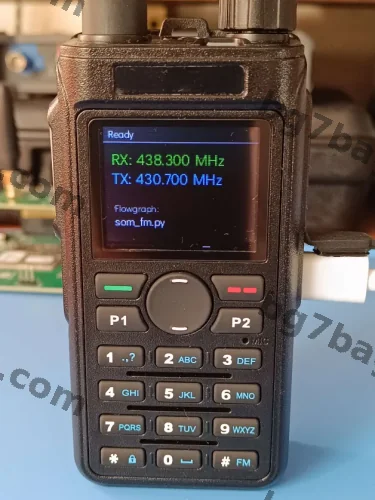
运行 OpenRTX 的手持电台——RX 438.300 MHz,TX 430.700 MHz
4. Getting started with Module17
4.1 Check compatibility
See the Module17 compatibility list (note whether TX and RX need inversion): https://wiki.m17foundation.org/index.php?title=Radio_compatibility_list
If your radio isn’t listed, you’ll need to verify it yourself; compatibility is not guaranteed.
4.2 Set your callsign
Press ENTER. Select “M17” and press ENTER. Select “Callsign” and press ENTER. Enter your callsign using the up/down keys to pick letters and numbers and the left/right keys to move the cursor. Press ENTER when done.
4.3 Adjust the baseband level
Use a small screwdriver to turn the multi-turn potentiometer.
4.4 Adjust the transmit level
The most reliable way is with SDR++ and an SDR receiver (for example, an RTL-SDR). Connect Module17 to your radio. Add the M17 demodulator module in SDR++, and tune it to your radio’s frequency. In the m17_decoder module, check “Show reference lines.” While pressing PTT, watch the constellation diagram and adjust the baseband TX level until the blue dots line up with the grey lines. Once the level is right, m17_decoder should decode your signal. If it can’t, check the transmit baseband polarity. If it still can’t, your radio may be incompatible.
4.5 Adjust the receive baseband level
Use an oscilloscope: the peak-to-peak voltage of the received baseband signal should be just under 3.3 V. Higher than that can damage the MCU’s I/O pins. If the level is right but the board still can’t decode, check the receive baseband polarity. If it still doesn’t work, Module17 may be incompatible with your radio.
5. A final word from the author
Others are welcome to build on my work and take it further.
- Module17 hardware: https://github.com/M17-Project/Module_17
- OpenRTX source: https://github.com/OpenRTX/OpenRTX
Thank you all.
Module17:让模拟电台用上 M17 数字模式的开发板
文 / BD7OTO
一、基础知识
2010年VK5DGR开源了Codec2的声码器,其输出速率只有700~3200bit/s。2012年诞生了FreeDV数字业余无线电项目,该项目以Codec 2语音编码器为基础,适用于短波通信,因短波频率偏低,声码器工作在低速率模式下。2019年,波兰华沙的SP5WWP发起了一个M17数字无线电协议项目。该项目同样以Codec 2语音编码器为基础,适用于VHF及更高频率通信,且完全开源,避开了商业协议(DMR、P25、C4FM、D-STAR等)的版权问题。自从20世纪90年代以来,业余无线电数字语音模式发展缓慢,大家更多的依赖于商业版数字无线电协议。M17为热爱无线电的软硬件开发人员提供了一个展示自我的平台。2024年12月,M17基金会成立,给热衷于M17的开发者带来了法律层面的保障。
二、技术要点
众所周知,DMR协议采用了TDMA技术,而M17采用了FDMA技术,两者不兼容。物理层采用4-FSK调制方式,在12.5 kHz信道带宽下信道速率为9600 bps。具体技术细节可参考英文版《M17 Protocol Specification Part I- Air Interface》。
作者很想说一句,别说英语不重要,对于深入搞理工科的人,英语才是母语。别说数学不重要,数学是理工科的基石。
OpenRTX是用于数字业余无线电的免费开源固件,目前也增加了对M17的支持。
三、如何玩M17
【3.1】原生支持M17的无线电产品型号如下:
- CS7000
- CS7000 Plus
CS7000和CS7000 Plus是Connect Systems提供的,运行OpenRTX固件,原生支持M17模式的手持无线电产品。
【3.2】部分支持DMR的无线电设备,可通过刷入OpenRTX固件和简易改装,亦可增加对M17模式的支持。
- 宝峰DM-1701 需要刷OpenRTX固件,改装教程:https://github.com/M17-Project/DM-1701_mod
- TYT MD-380、MD-390 需要刷OpenRTX固件,改装教程:https://openrtx.org/#/M17/md380_mods
- Retevis RT3(UHF) 与MD-380类似
- TYT MD-UV380、MD-UV390 需要刷OpenRTX固件,改装教程:https://openrtx.org/#/M17/mduv380_mods
- Retevis RT3S 需要刷OpenRTX固件
【3.3】这是本文的重点。
部分普通模拟FM无线电设备,可以使用Module17来实现对M17模式的支持。Module17是一款支持M17数字模式紧凑型调制器,给传统模拟FM电台设备(支持9600比特率)以支持M17的机会。作者制作的Module17开发板过程如上图所示。
部分支持Module17的模拟无线电台设备可参考:https://wiki.m17foundation.org/index.php?title=Radio_compatibility_list
供电:采用USB Type-B接口(即打印机方口)供电。目前Type-C供电协议混乱,个人考虑再三,选择放弃。
DB9连接器:用于Module17连接无线电台设备的接口。
以八重洲FTM系列无线电台设备为例,连接线定义如上图所示。
话咪接口:用于连接宝峰(Baofeng)品牌话咪(自带扬声器),其它品牌话咪产品尚未测试。
音量旋钮:位于左下角,用于电源开关和调整话咪扬声器的音量。
问题1:八重洲的1200bps封包数据输出与9600bps封包数据输出区别?
1200bps封包数据输出常用于VHF APRS,通过两个音频频率传输数据,该模式会经过预加重在内的音频AF滤波。9600bps封包数据可以绕过AF滤波,可确保信号传输无失真。
问题2:八重洲的DIG和PKT有什么区别?
| DIG模式 | PKT模式(DIG的子类) | |
|---|---|---|
| 核心用途 | 兼容数字语音、多种数字调制信号解调 | 仅面向1200/9600bps分组数据传输 |
| 典型场景 | C4FM数字语音通联、FT8数字弱信号通联 | APRS位置上报、无线数传报文收发 |
| 硬件依赖 | 电台内置DSP即可直接使用基础功能 | 需外接TNC/数传适配器连接电脑配合软件使用 |
| 速率支持 | 无固定速率,随不同数字协议变化 | 固定支持1200bps(常规VHF)和9600bps(高速数传) |
【3.4】未来机型。
M17团队目前正在开发LinHT。LinHT是一款开源的,基于Linux的SDR手持无线电产品,外观与Retevis C62主板类似。
四、开始使用Module17
【4.1】检查Module17与您的无线电设备兼容性。
Module17兼容性列表(注意TX与RX是否需要反相)可访问:https://wiki.m17foundation.org/index.php?title=Radio_compatibility_list
如果您的无线电设备不在列表中,需要自行验证,不保证兼容。
【4.2】配置呼号
按ENTER键。选择“M17”并按ENTER键。选择“呼号”并按ENTER键。输入您的呼号时,使用上下按键选择字母和数字,使用左右键将光标向左右方向移动。完成后按ENTER键。
【4.3】调整基带电平
电平调节,可用小螺丝刀,调节多圈电位器完成。
【4.4】调整发射电平
调整TX基带信号电平最可靠的方法是使用SDR++和SDR接收器(例如RTL-SDR)。将Module17连接到您的无线电台设备。将M17解调器模块添加到您的SDR++接口,并将其调谐到您收音机的频率。在您添加的m17_decoder模块中,勾选“显示参考线”复选框。按下PTT键的同时,查看m17_decoder模块的符号图,并调整基带发射电平,直到背景中的蓝点与灰线对齐。当基带电平调整正确后,m17_decoder应该能够正确解码您的信号。如果解码失败,请检查发射机的基带极性。如果仍然无法解码,则可能是您的无线电设备不兼容。
【4.5】调整接收基带电平
是用示波器观察接收基带信号的峰峰值电压略低于3.3V。高于此值可能会损坏MCU的IO口。如果信号已调至合适电平,但电路板无法解调输入信号,请检查接收基带信号的极性。如果仍然无效,那么Module17与您的无线电设备可能不兼容。
五、作者最后想说的话
大家可以在作者基础上继续研究下去,发扬光大。
- Module17硬件:https://github.com/M17-Project/Module_17
- OpenRTX源程序:https://github.com/OpenRTX/OpenRTX
谢谢大家。